Overview
The Data Acquisition System (DAQ) is responsible for the collection and transmission of wanted data on the UTDallas FSAE Electric Vehicle. This will allow us to analyze car performance in multiple ways, see errors in real time, and display useful information to the driver. The DAQ is composed of the following devices:
- 4x Wheel based CANpute nodes
- 1x ride height CANpute node
- 1x Dash CANpute node
- 1x Dash Display
- 1x VCU
- 3x PDMs
- 1x Raspi CM5 Central Node
- 1x Omni Directional Antenna
- Various Sensors
Design
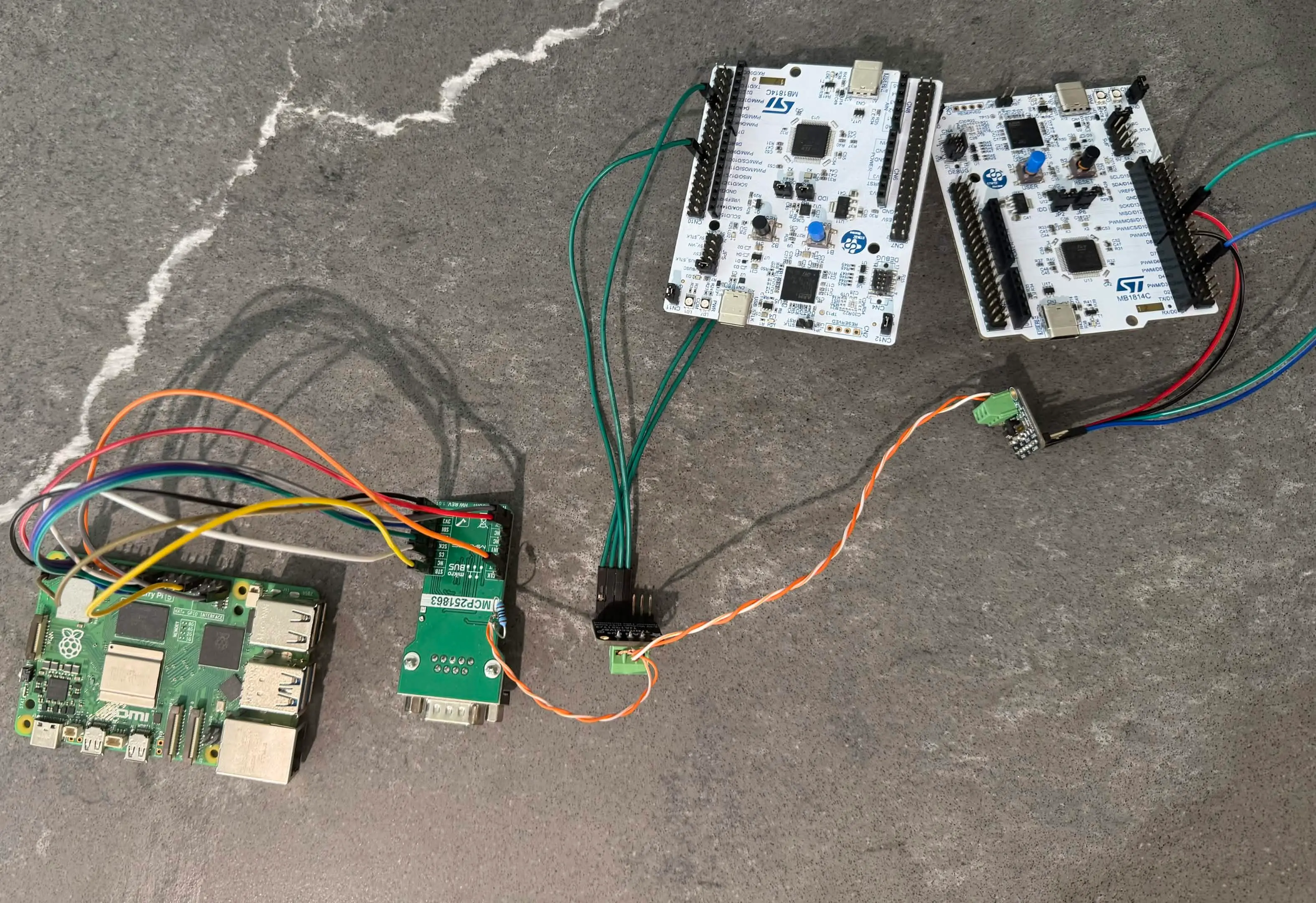
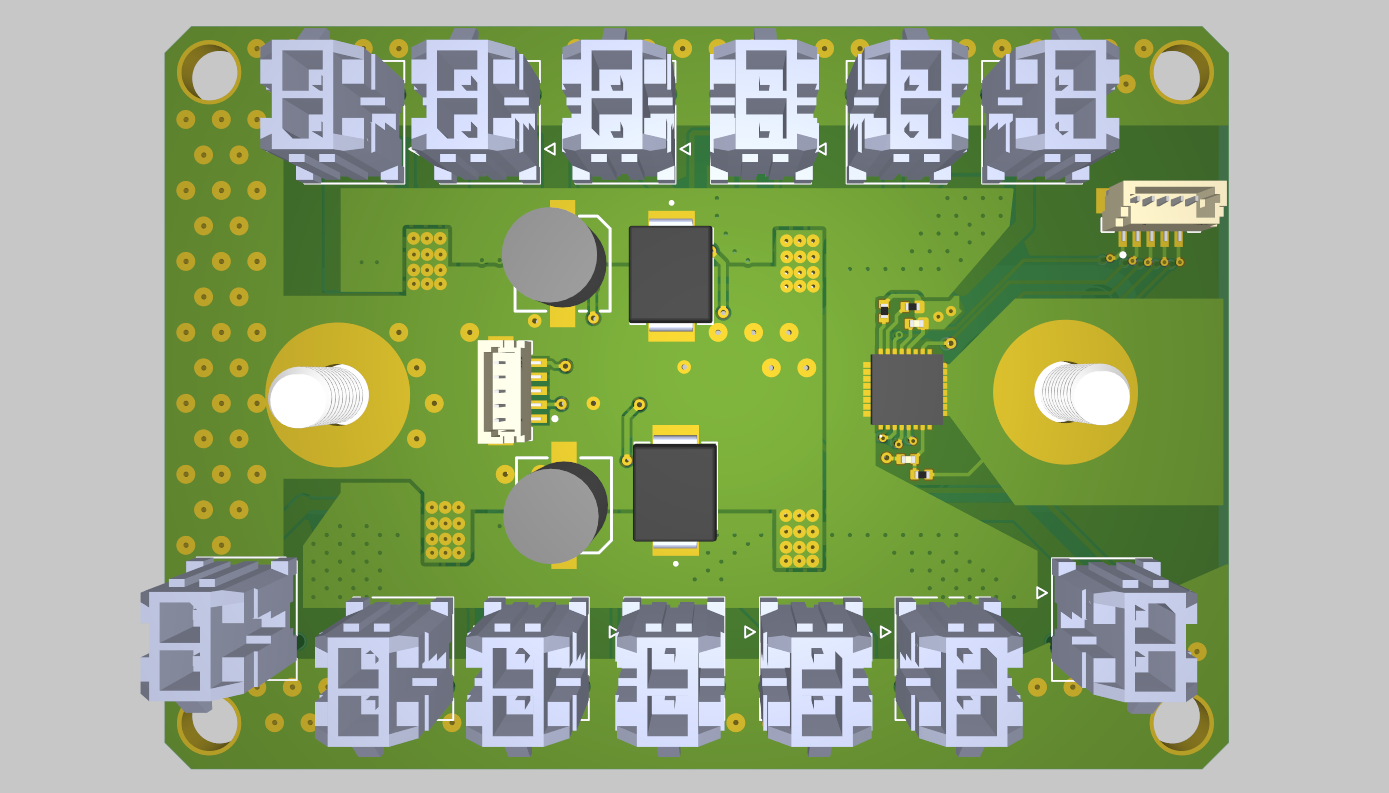
When designing the DAQ system, I was really focused on keeping the wiring harness clean and organized. To do this, I avoided using home runs for all of the sensors on the car, since there will be dozens of them, and having hundreds of wires for the DAQ alone would be impractical. Instead, I created the CANpute node device (seen below), which is an STM32-H5 based device that has all of the nearest sensors wired directly to it. There is one of these nodes at each wheel, reading the tire temperature, brake temperature, wheel speed, and other nearby sensors. The CANpute nodes are daisy-chained together for both CAN bus communication and power distribution. That means from wheel to wheel there is a single CAT6A cable, while all the sensors are connected directly to the CANpute node. There is also a node in the dash to convert the CAN bus signals to the I2C needed for the display. There are 2 CANFD lines that each node is on, one for the actual data and normal information, and another for higher priority system control, bootloading, and error reporting. On both of these lines is the DAQ Central Node, a Raspberry Pi CM5 based device that acts as the central hub for the DAQ system. It reads all of the sensor data from the CAN bus, records, transmits, and presents the data on a web interface. Learn more about that here.
Hardware
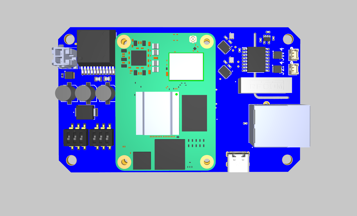
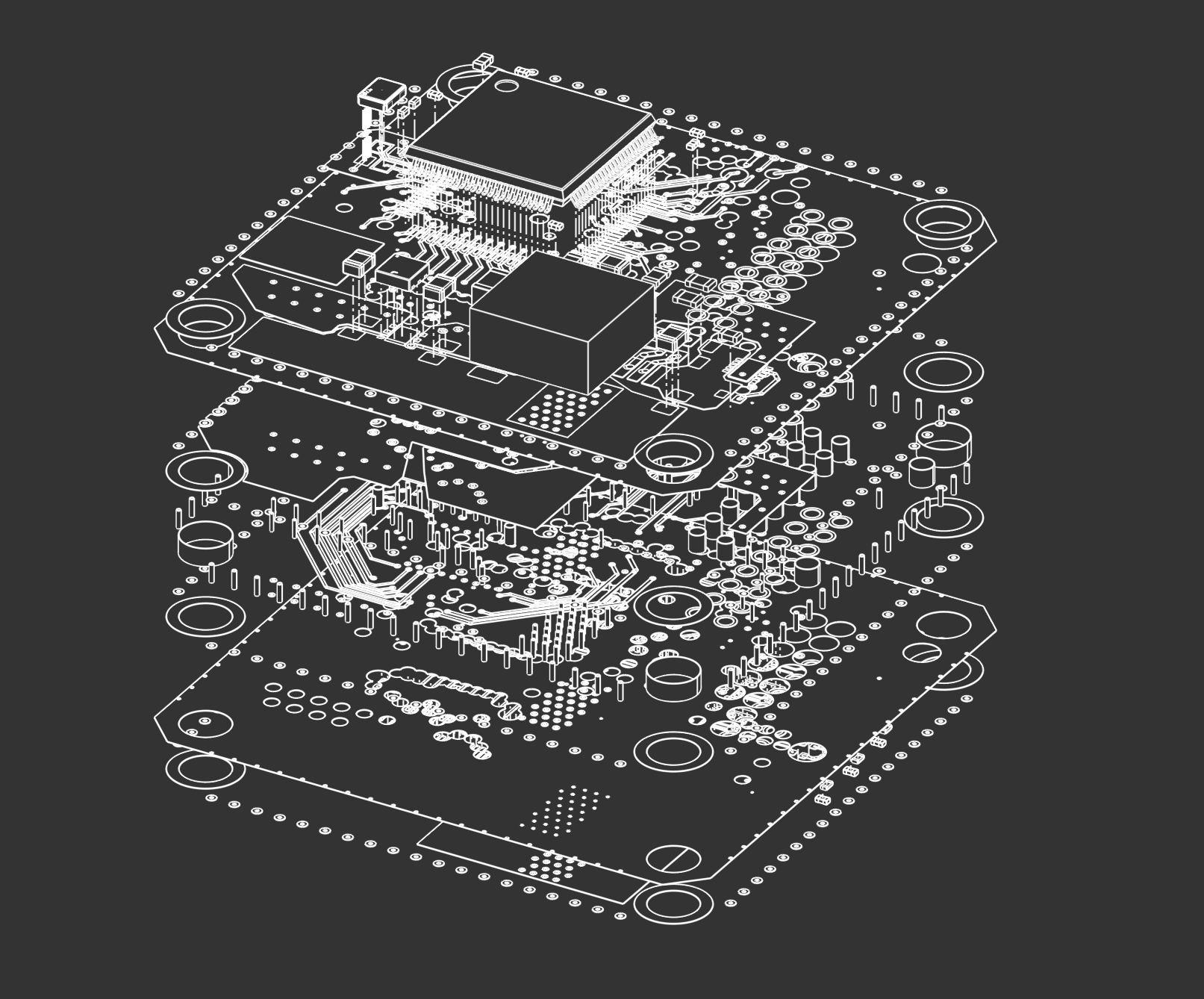
The CANpute note is shown below. It is comprised of an STM32H533re, 12-5v buck, 5-3v LDO, efuse, molex connectors, and CANFD transceivers.
Firmware
The application firmware for the CANpute node is written in C using the STM32Cube toolset. The code is available on GitHub. Each node runs identical firmware, in which each node identifies itself by reading its UID (Unique Identifier), and then assigns a unique node ID based on that UID. This node ID is used in my bespoke CAN bus protocol (The DFR CAN Standard). Alongside the application firmware, I wrote my own FDCAN bootloader for over the air updates, allowing me to update the firmware on any node without needing to disconnect it from the bus, or having to access it physically. Read more about that here.